This article orients you to the Bloodhound by identifying the most basic main components on the unit – areas of the Bloodhound with which you must be familiar in order to understand the proper operation of the unit.
PREREQUSITES:
There are no prerequisites for this article. You do not even need to have received your Bloodhound yet.
GENERAL INFORMATION:
1) THE BLOODHOUND – CLOSED: The Bloodhound will arrive closed as in the figure below.
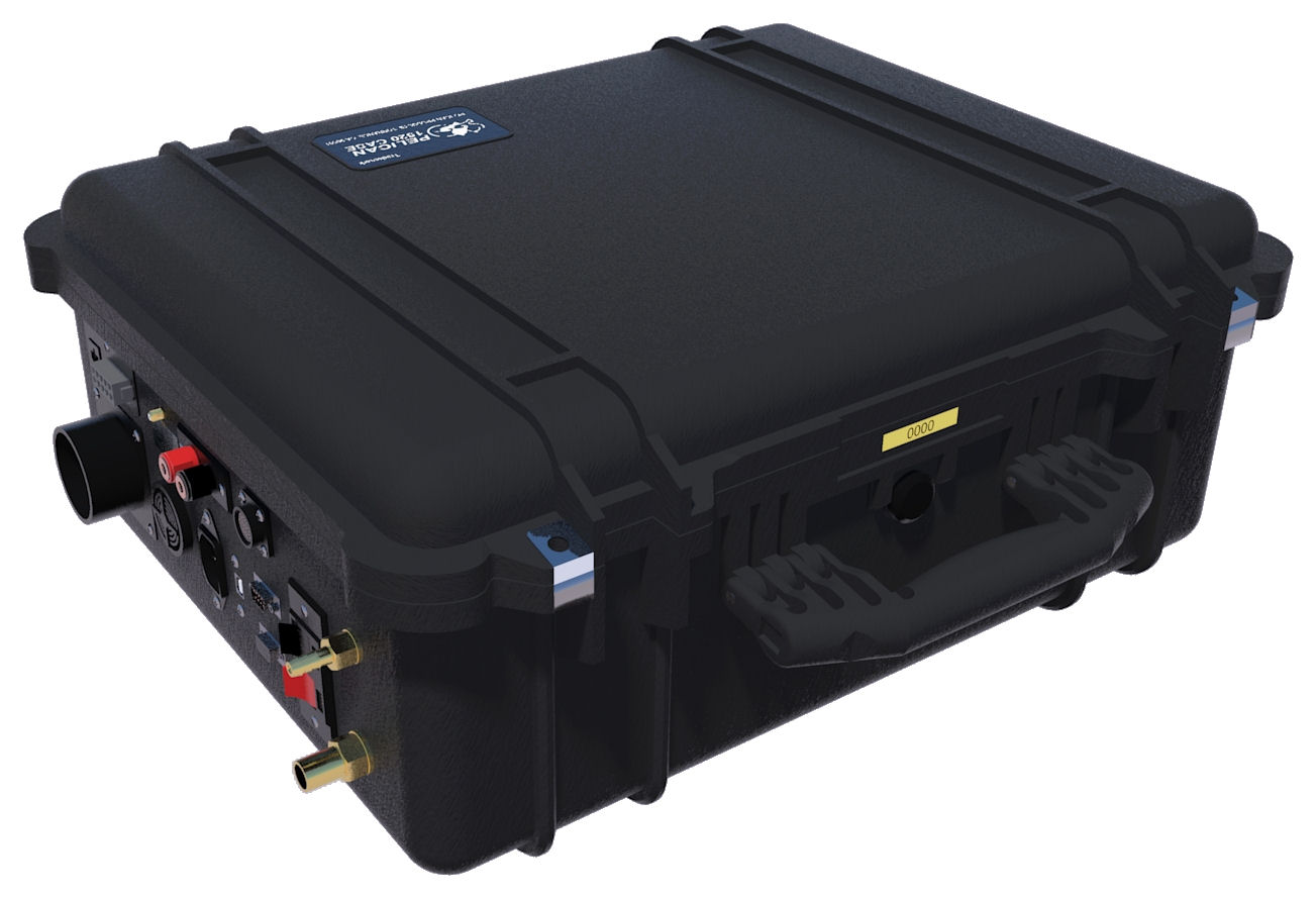
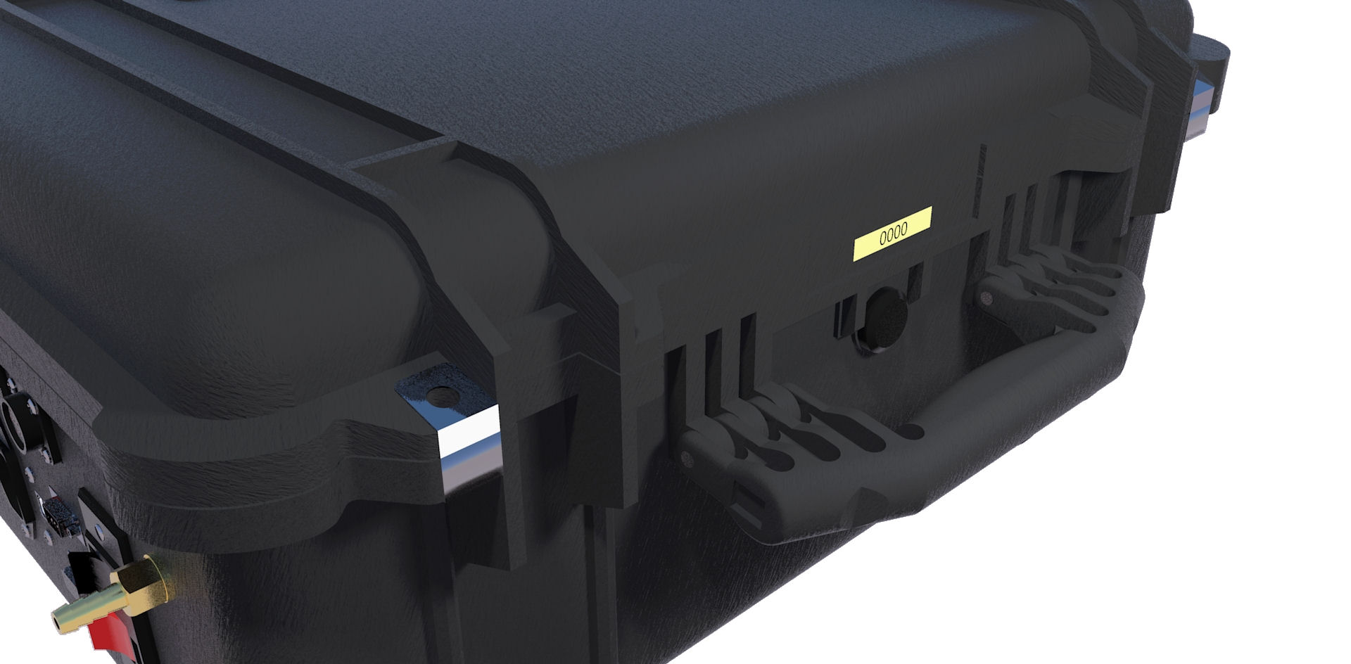
2) CARRYING HANDLE: If you need to move or relocate the Bloodhound, make sure the lid is closed and fastened with the two Pelican fastners, and use the carrying handle shown in the figure below to carry the Bloodhound. Note the yellow serial-number tag fastened under the handle. If you call for technical support, you will be asked for this number. To open the Bloodhound, unsecure the two Pelican latches, and lift the lid.
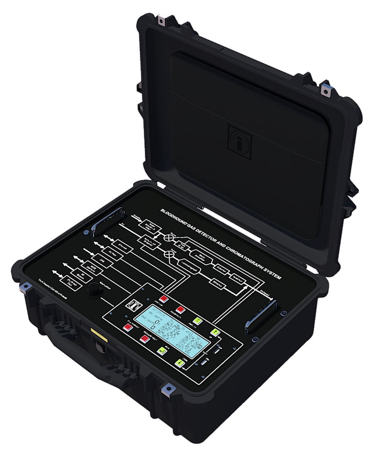
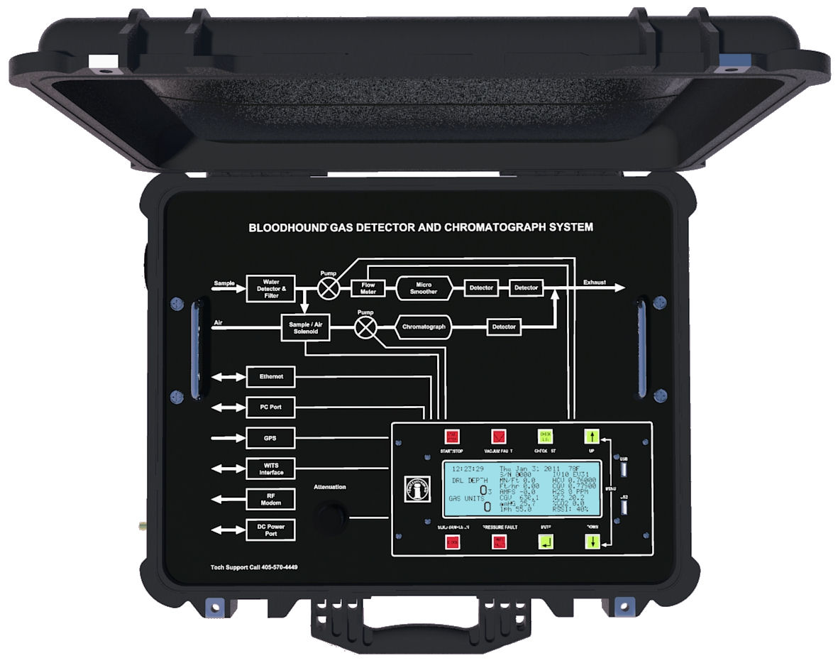
3) THE BLOODHOUND – OPEN: The overall Bloodhound logging system is shown below, with the lid open, reveailing the face of the Bloodhound, the logic and control panel on the Bloodhound, and the knob control. You can also see the screen-printed diagrams showing the Bloodhound’s gas flow circuits, and the input/output options on the Bloodhound.
4) LID POUCH: The image below shows the location of the pouch. Inside this pouch are a copy of the user manual for the Bloodhound, a GPRS antenna, a power cord, and a number of other items of use.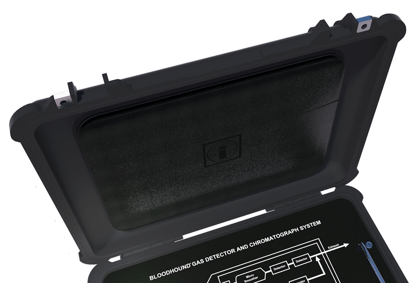
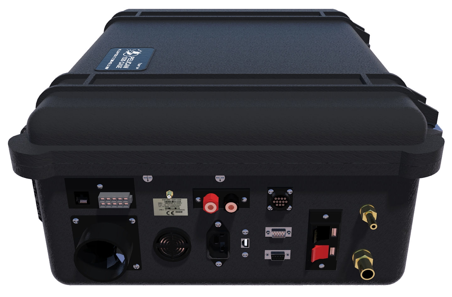
5) CONNECTIONS: If you look on the left-hand side of the Bloodhound (outside of the actual case), you will see a number of ports, tubes, and connectors. This is the “connections” area on the Bloodhound, where you connect your sample inlet, exhaust, WITS, an on-site computer, network, antenna, etc.
6) BLOODHOUND FACE: Below is a figure showing the face of the Bloodhound. When we talk about the “face”, we refer to the screen-printed area under the lid, the “logic control” section, the knob, the “chrome protection handles” on the face, and the screws located just to the outside of the chrome protection handles.
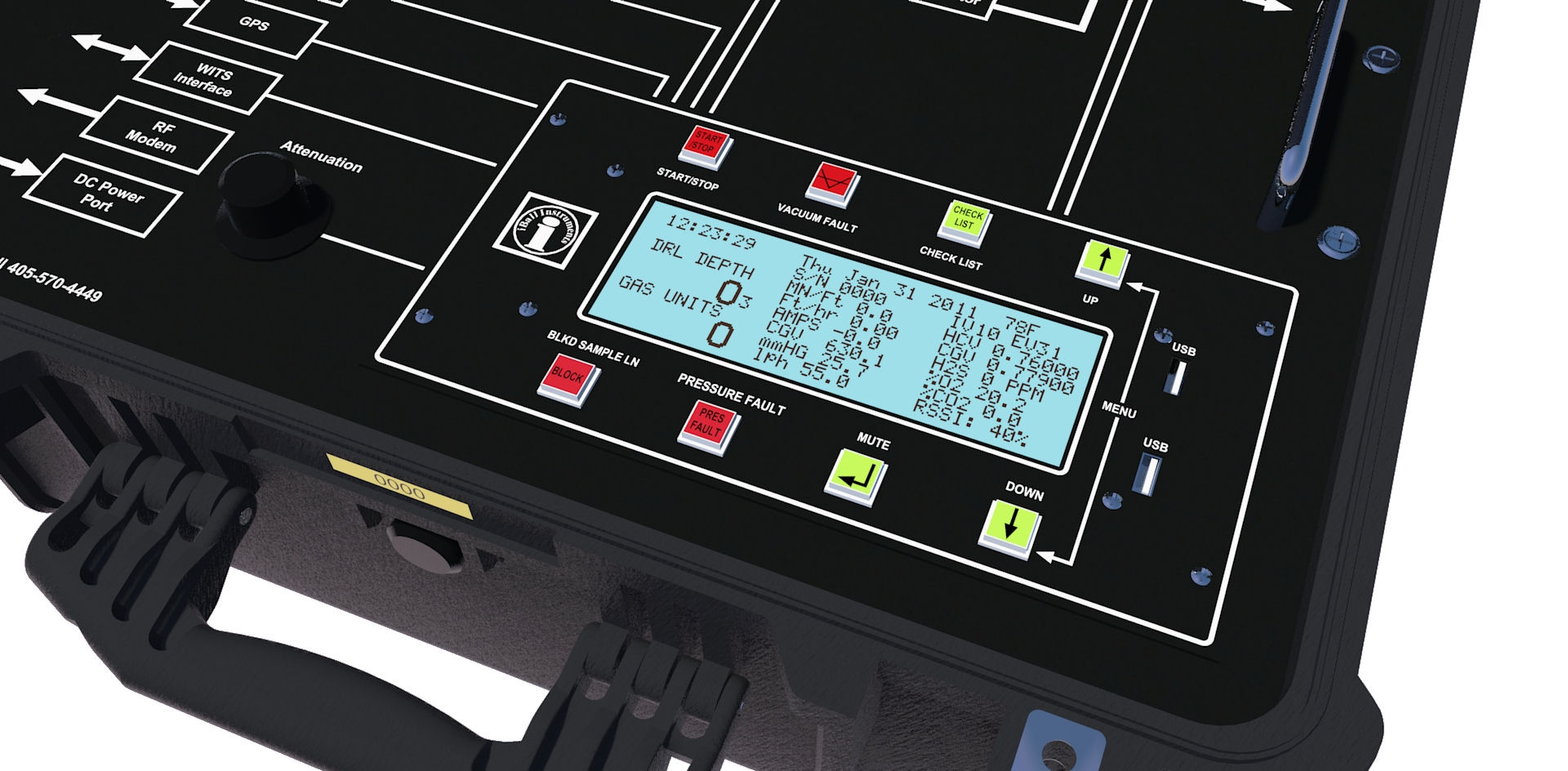
7) LOGIC CONTROL: The figure below highlights the “Logic Control” section of the Bloodhound. This section encompasses the LCD readout on the face of the Bloodhound, the eight (8) control buttons surrounding this LCD panel, the USB flash drive (not shown below), and the two (2) USB ports on the face of the Bloodhound, and the knob to the left of the control panel.
And that is a summary of the Bloodhound’s major components!