This article discusses using iBall Instruments Gas Chart Software to remotely connect to a Bloodhound and set peaks. By “Remote” it implies that you are connected to the Bloodhound over a network – it can be a Local Area Network (in the same trailer as the Bloodhound even) or the Internet.
PREREQUSITES:
These are the *recommended* prerequisites for using this article – they are not required, but are helpful:
1) It is valuable to have the Bloodhound in front of you for this tour. 2) It is also valuable to have the Bloodhound powered on for this tour.
INFORMATION:
1) The Bloodhound’s main region, excluding the LCD and Button/Key Panel as shown in the figure below:
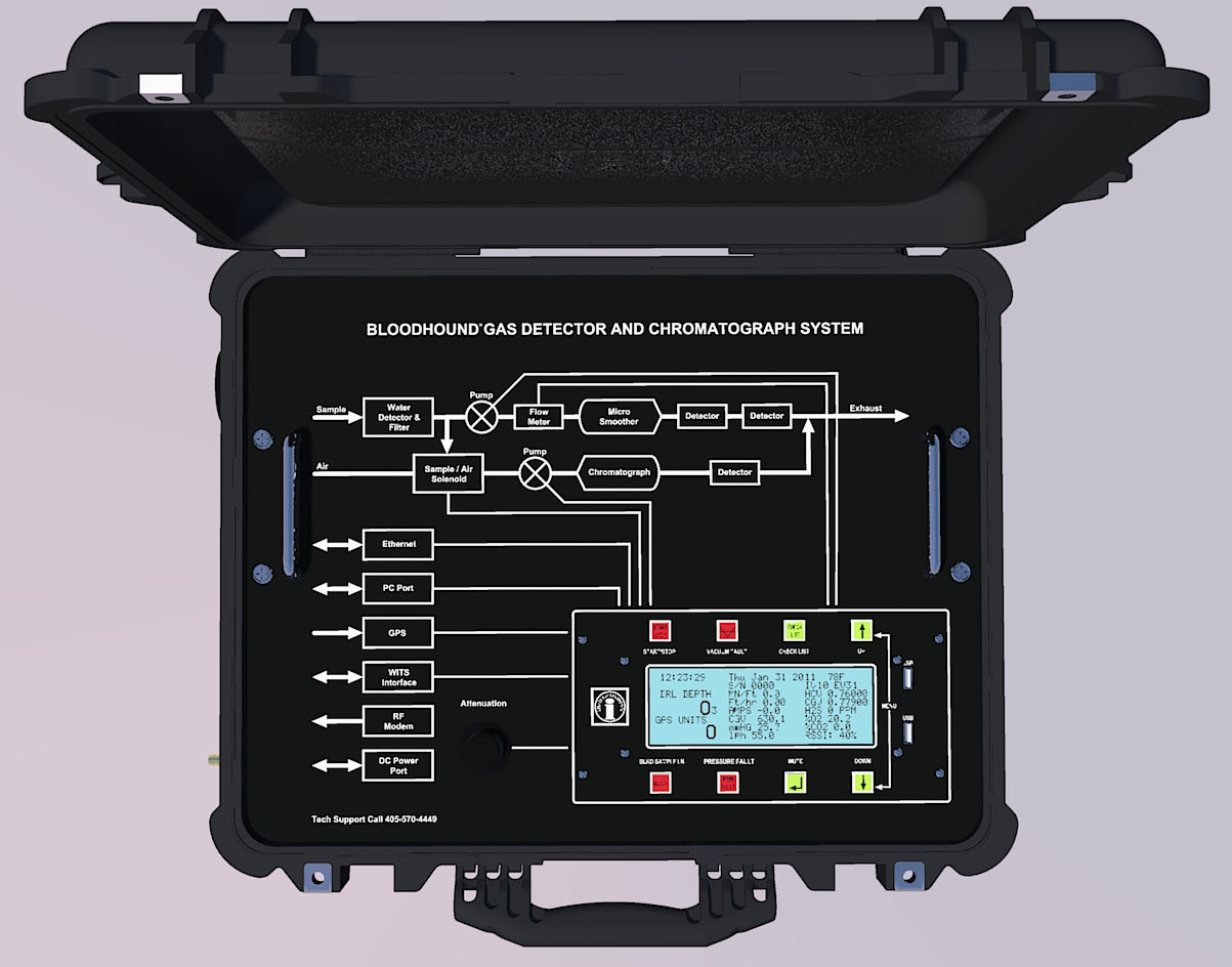
a) First take note of the screen-printed diagrams just below the instrument’s name. This are explains the two distinct gas circuits/instruments that are the Bloodhound. On the top, you see defined the Total Gas circuit, and the second line illustrates the Chromatograph circuit.
NOTE: While the Total Gas/O2/CO2/H2S circuit is real-time, the Chromatograph circuit is a “snapshot” system, with a solenoid kicking off for (by default) five (5) seconds once every eight (8) minutes to populate the Chromatograph column with a fresh sample from the inlet line.
A close-up of this screen printing is illustrated in the figure below:

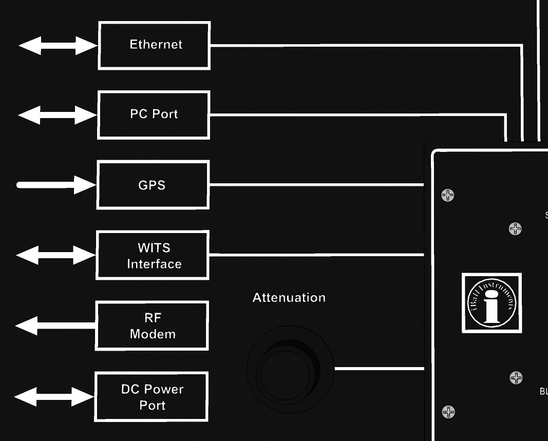
b) Next, if you look down and left from this section of the face of the Bloodhound, you will find additional screen-printed information that describes the Bloodhound’s interfaces, including: The bi-directional Network (Ethernet) port, the bi-directional PC (USB/Serial) port, the bi-directional WITS (via NULL Modem or RS422) Interface, the mostly uni- directional GPRS/RF Antenna interface (capable of bi-directional communication for admin and remote operation cases), and the DC Power out port. The figure below enlarges this section of the screen-printed area:
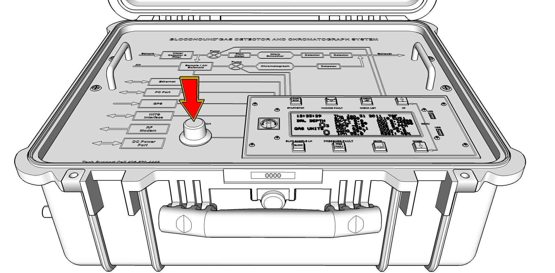
c) Also in this section is the Bloodhound’s control knob, which is used to zero gases, calibrate items, operate menus, set attenuation, and more. Its location is illustrated below:
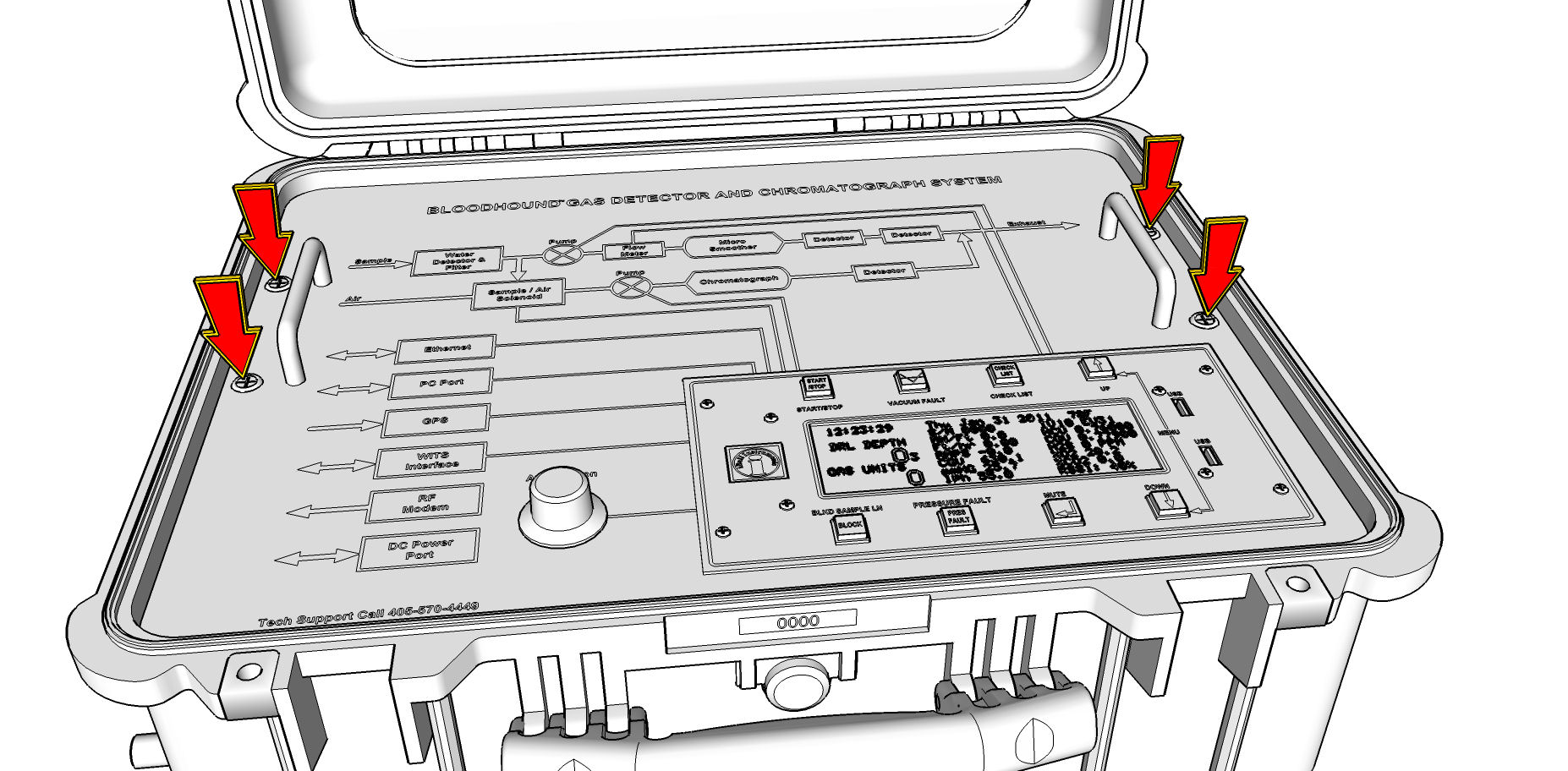
d) Finally, in this main section, you will also find the four (4) Philips-Head screws just outside of the protection handles. You may need to remove these to lift out the Bloodhound’s face if you have to change a pump, or inspect internal filters, connections and the like. The location of these screws is here:
2) Next, we move into the Bloodhounds main “Logic Control and Feedback” area. This is the section of the face located in the lower-right hand portion of the face, and it includes the eight (8) control buttons, the LCD, and the surface USB ports. We will begin by focusing on the keys/buttons in this area:
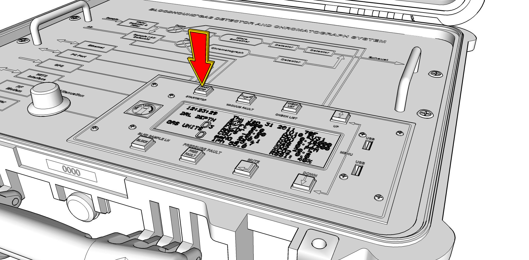
a) The START/STOP button (as illustrated below) is kind of like an “escape key” for the Bloodhound. It can be used to exit any menu, or to power off the Bloodhound after pulling the power cord. It has many contextual functions as well.
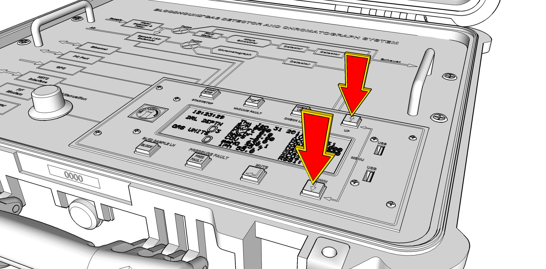
b) The “UP” and “DOWN” arrow keys on the right hand side of the Bloodhound are primarily menu and setup keys. In fact, if you press them together, you will notice that the LCD changes and you are shown the “SETUP” menu. When in this menu, you can cycle through the items, or change values using the UP and DOWN keys. The location of these keys is illustrated in the figure below:
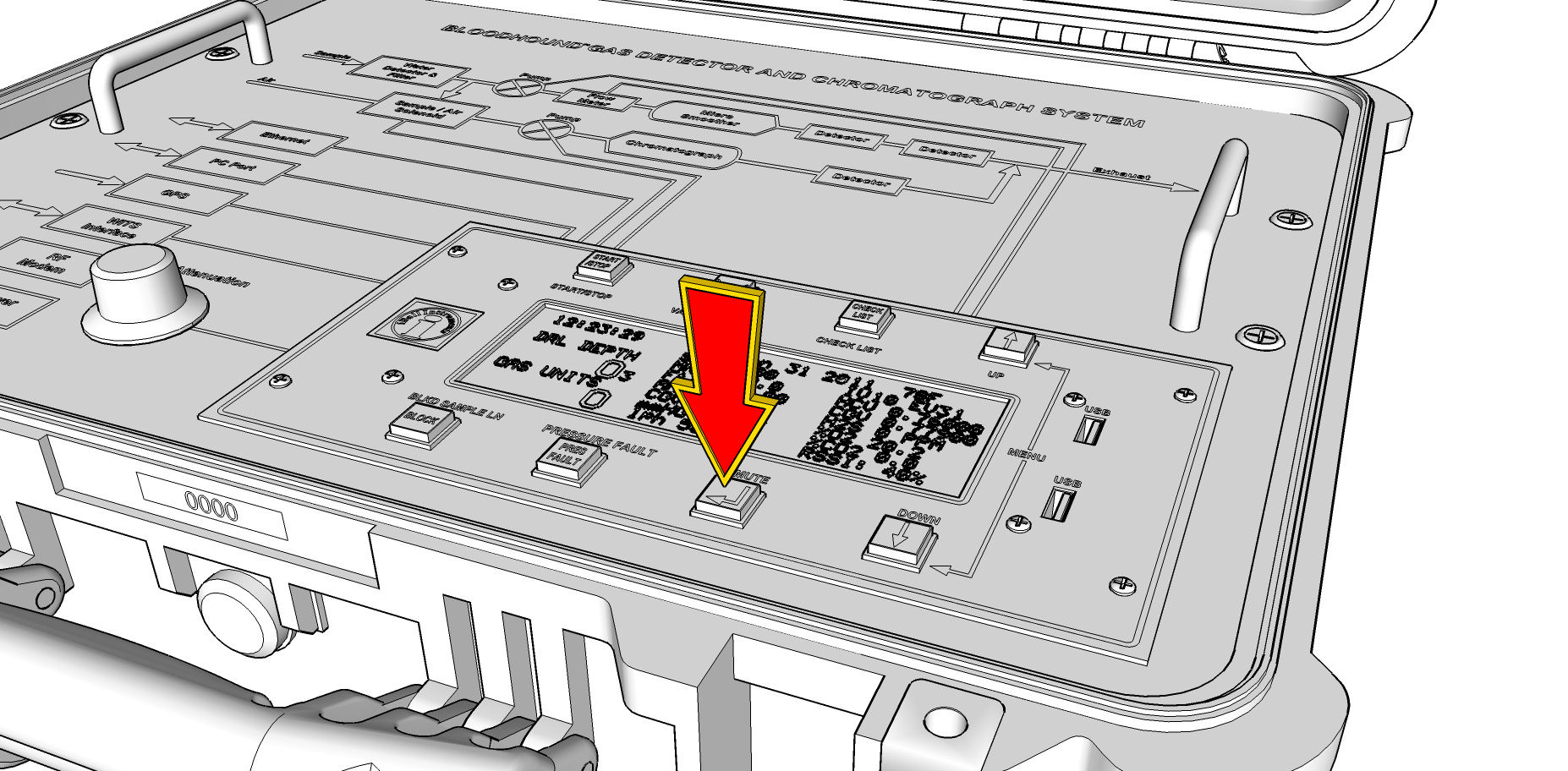
c) The “MUTE” key will toggle the three MUTE states for any alarm (ON / MUTED TEMPORARILY / MUTED PERMANENTLY). It also is the “ENTER” key whenever in a menu. If you look closely at the key itself, you will see the ANSI standard symbol for “ENTER” printed on it. This key’s location is illustrated in the figure below:
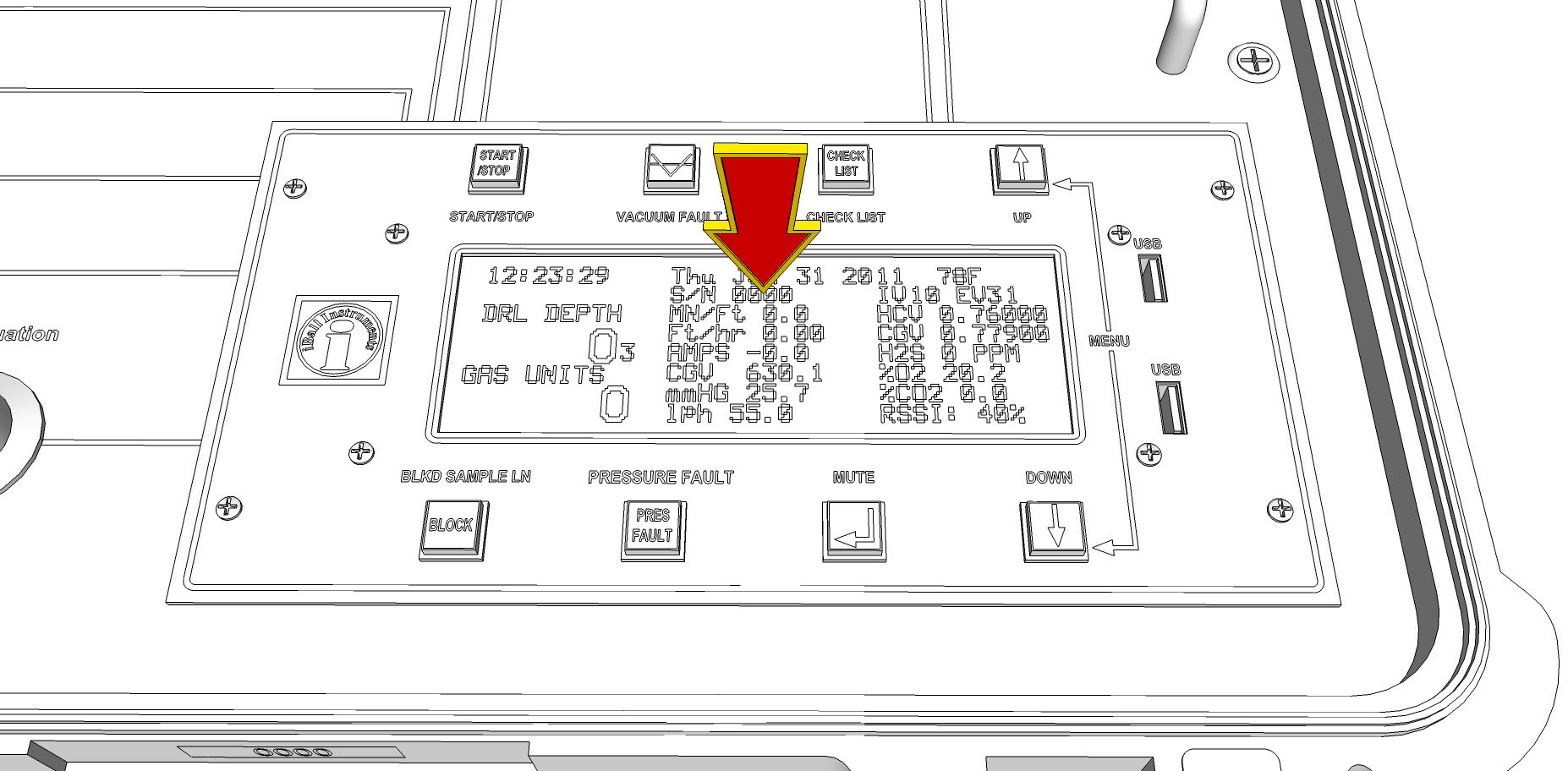
3) Now we move on to the LCD itself, where a number of important piece of data and feedback to the on-site user can be found:
a) First, let’s look at the top two lines. Here you will find the time and date currently set on the Bloodhound, the temperature of the Bloodhound, the Serial Number of the Bloodhound (also printed on a yellow sticker near the carrying handle on the Bloodhound’s case), and the two versions of firmware that are on the Bloodhound. These are located in the area identified below:
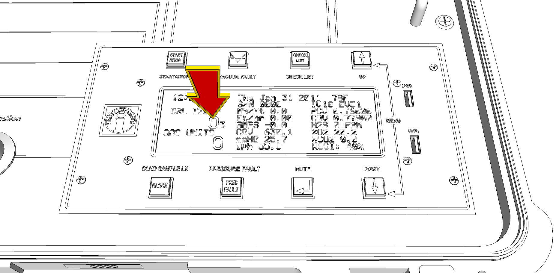
b) On the bottom-left of the LCD in large numbers are the Drill Depth (provided either via WITS or a Geolograph), and the real-time Total Gas Units (TG). They can be found here:
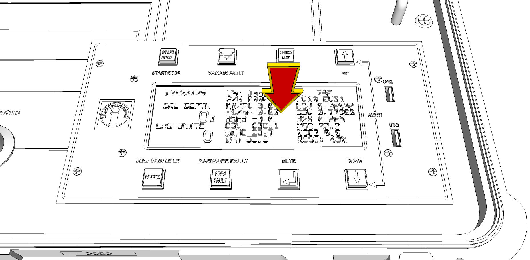
c) The remaining table of information (excluding the bottom-right field), contains a number of “vitals and non-vitals” for the Bloodhound, including some information on ROP, (if you have a DC Cavitator) the Amperage draw on the power supply, voltages on the various sensors (primarily used in troubleshooting), (if you have this option turned on) the H2S PPM, percentages of mix-gases, mmHG (which is actually vacuum on the sample line), and the flow rate. The section where all of this information is displayed in a table is illustrated in the figure below:
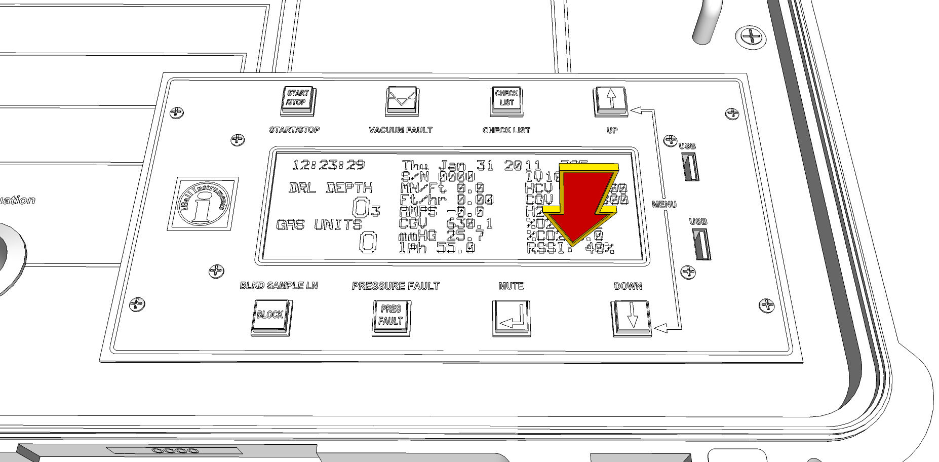
d) Last, but certainly very important is the bottom-right field. This field “rotates” through a number of important pieces of data including cell phone signal strength (RSSI %), if you are using a Network, the IP Address and port that the Bloodhound has allocated, countdowns to various important events (such as next Chromatograph injection time, or modem attempt to connect time), and others. This field is located here:
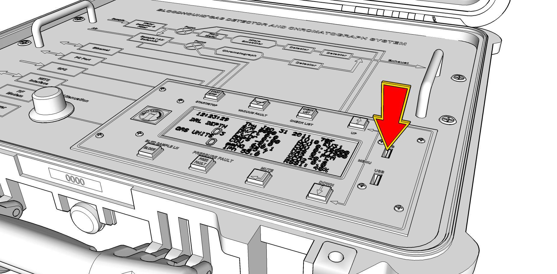
4) Moving on from the LCD, we now come to the USB Ports on the right-hand side of the logical portion of the BLoodhound. It is important to note that only the top port is functional – the other port is only a place to store a spare USB Flash Drive if you would like to. Many people even cover the bottom port with black electrical tape to avoid trying to use it as a data port. You will want to leave the USB Flash Drive plugged into this port for as much of the drilling duration of the well as possible, because this USB Flash Drive contains one of the two primary backups of data that the Bloodhound produces. Even if it goes offline, even if your Gas Chart fails, you can still go to this drive after the fact to get your data; hence its importance. The port in which you should find a USB Flash Drive is illustrated below:
There you have it – a tour of the Bloodhound’s top face.