This article specifically covers one possible scenario in rig-up. While this is generally one of the simpler scenarios, it is also one of the most common.
PREREQUSITES:
There are no prerequisites for thie article – this is academic only.
RECOMMENDED RIG-UP:
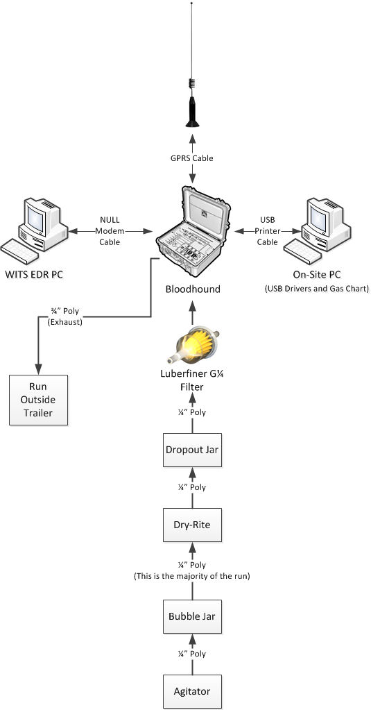
1) Below is a diagram depicting the recommended rig-up of the Bloodhound in the trailer:
2) Take a look at the left hand side of the Bloodhound where all of the connections are located (see the figure below for what this looks like):
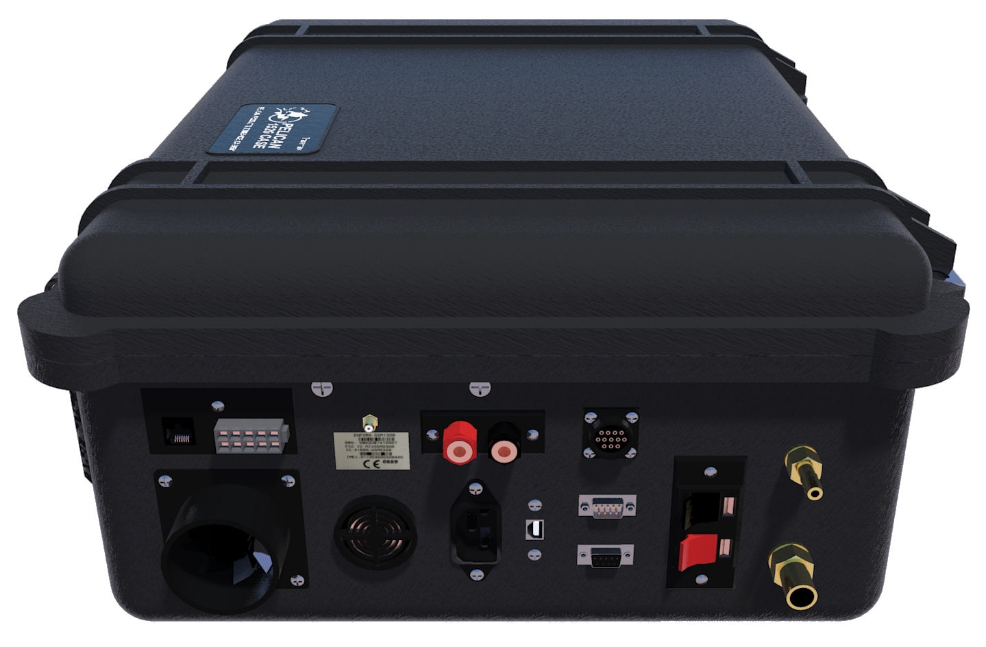
3) The connections used in this rig-up example are the 1/4″ Sample Inlet, the 3/4″ exhaust outlet, the 9-pin RS/232 WITS connection, the USB connection, the 120V/AC power connection (implied), and the GPRS radio antenna connection.
4) In addition to the connection, it is important to note that the filters included in the Bloodhound (see image below for example) need to be installed on the Bloodhound’s ventilation port (bottom left) and the 1/4″ inlet barb before running your line:
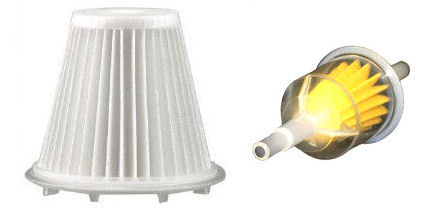
NOTE: As of August, 2013, the “fuel filter” shown above-right has been replaced with a 0.45-micron “Disc-Type” filter. You will find it in the case in place of this fuel filter. Rig it up in the same manner that you would the fuel filter – on the outside of the Bloodhound between your inlet line from the trap and the Bloodhound’s brass-inlet barb.
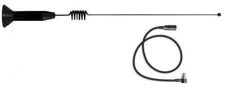
5) CONNECT GPRS ANTENNA: The easiest way to connect your Bloodhound to the Internet is by using the internal GPRS data modem. As long as you have AT&T digital service in the area this will work 90% of the time. Simply connect the GPRS antenna (included in the pouch on the underside of the lid of the Bloodhound) and mount the antenna as far away from the Bloodhound as possible (to avoid RF noise from the antenna). The antenna is shown in the figure below:
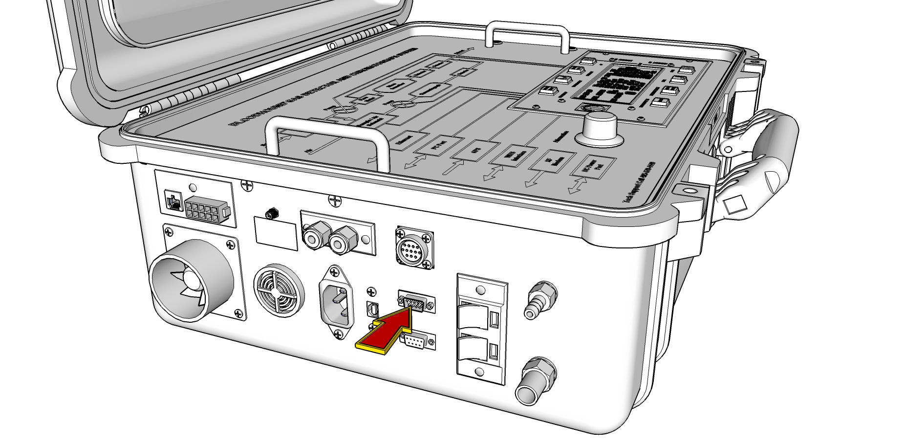
6) CONNECTING TO WITS: Connect the WITS EDR to the Bloodhound using a Null Modem Cable and the 9-pin RS/232 WITS port on the Bloodhound (shown in the figure below). For more information on connecting WITS to the Bloodhound, see the article link entitled “Connections – Hooking up WITS to the Bloodhound” in the section below called, “OTHER ARTICLES OF INTEREST”:
7) SETUP USB connection AND GAS CHART: If you are using iBall Instruments Gas Chart Software, you need to get a local computer and set it up with this software and make the connection in between the Bloodhound and the computer:
a) INSTALL USB DRIVERS: BEFORE connecting the USB printer cable between the Bloodhound and the Windows computer that will be running Gas Chart, you need to first install the USB drivers. If you don’t know how to do this, consult the link under the article entitled, “Connecting your Computer to the Bloodhound via USB Printer Cable” in the section below called, “OTHER ARTICLES OF INTEREST”.
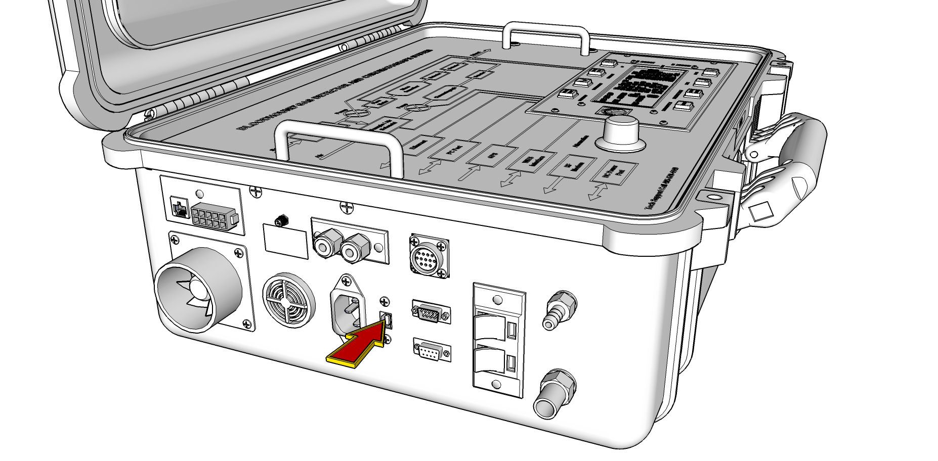
b) CONNECT THE BLOODHOUND AND THE COMPUTER: Now, connect the computer and the Bloodhound via the USB Printer Cable, using the port on the Bloodhound identified in the figure below:
c) INSTALL GAS CHART: Finally, you need to install iBall Instruments Gas Chart on the computer. If you do not know how to do this, consult the link under the article entitled, “How to Download and Install iBall Instruments Gas Chart Software” in the section below called, “OTHER ARTICLES OF INTEREST”.
8) RIG UP THE SAMPLE LINE (RECOMMENDATIONS): The Bloodhound is a highly resilient machine because of the bank of IR sensors; however, the tradeoff is that it is highly susceptible to moisture and does not tolerate flooding. The following advice for rig-up will help you create a sample line that is easier to troubleshoot, and will reasonably protect the Bloodhound from flooding:
a) REMINDER: Make sure the 1/4″ Luberfiner filter is plugged into the sample inlet line first. This represents the absolute minimum and last line of protection to the Bloodhound. It also makes removal of the sample line for gas zeroing, and testing much easier.
b) QUARTER-INCH POLY LINE: We recommend 1/4″ poly line as the main sample line. There are many reasons for this including cost, a well-known understanding of this type of line on the Bloodhound, and ease-of-use.
c) DROPOUT JAR: We recommend a dropout jar inside the trailer and near the Bloodhound to catch any particulate leftovers from the Dry-Rite which is immediately upstream in the line. It also serves as a visual aid in the case that any flooding has started to occur.
d) DRY-RITE: To avoid moisture contamination in the Bloodhound, we recommend a Dry-Rite column in the line (usually inside the trailer) immediately upstream from the dropout jar.
e) LONG RUN POLY: For the long run of poly line from the trailer to the bubble jar (which is out near the trap), use a continuous 1/4″ poly line that is not subject to direclty being run over, walked on, or in any way “messed with”.
f) BUBBLE JAR: Near the trap, you want a bubble jar, filled with anti-freeze or some other non- contaminant/unfreezable substance. This will help you to troubleshoot any line leakage.
g) AGITATOR: Finally, you make the connection to the agitator using whatever method you have chosen.
9) RIG UP THE EXHAUST LINE (RECOMMENDATIONS): This is critical – do not forget to use a 3/4″ poly line exhaust tube (or any appropriate line of the correct dimension) to exhaust the Bloodhound well outside of the trailer.
And that is a high-level picture of how to rig-up the Bloodhound!